I’ve written about monitoring temperature around the house before.
The solution I wrote about then is still working well.
But, more recently, I wanted to not only update the system, play with some new things, but also a minor underlying driver was the desire to be able to see when the boiler was on, and where the heat was being sent; radiators and/or hot water.
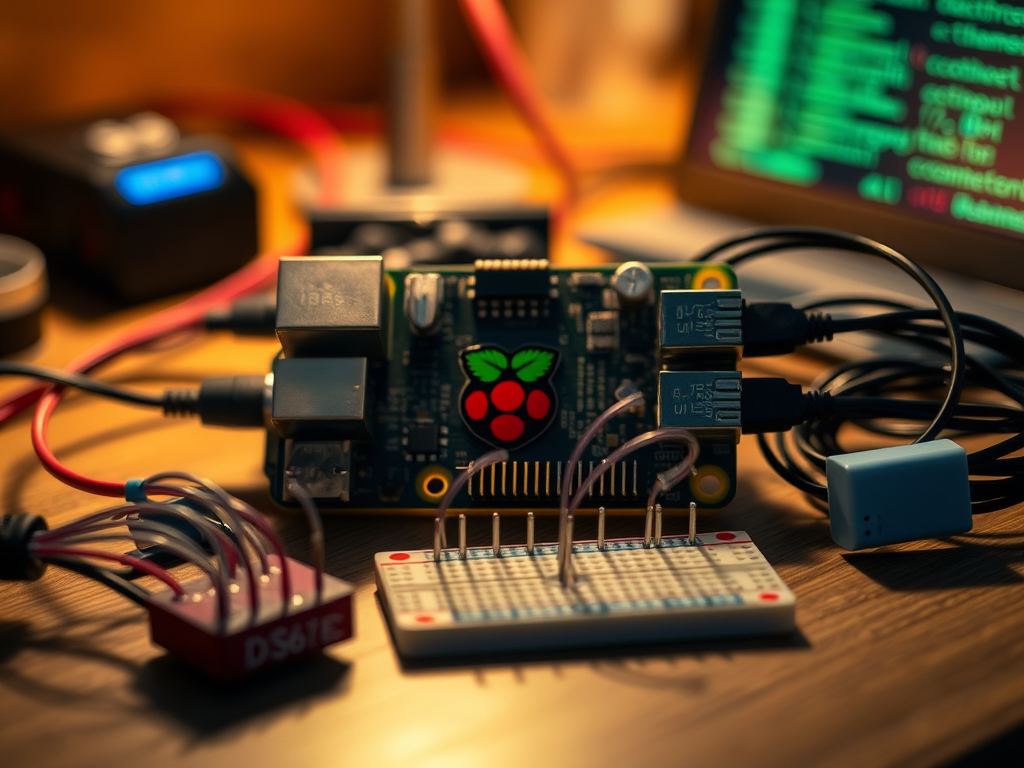
I had also been looking for a reason to have a play with Raspberry Pi Pico and I’d found that it’s fairly trivial to use DS18B20 sensors on one of the Pico’s GPIO pins.
Hardware
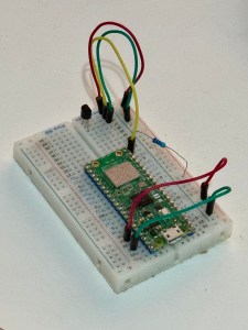
So, I ordered a Pico2W, a small breadboard to prototype it, a solderable breadboard for the final item, and some DS18B20 sensors.
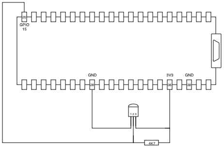
The DS18B20 have a low power requirement, and so with the Pico powered by a suitable power supply, 3V3 can be taken from pin 36, with ground on any of the GND pins. I used pin 38 in reality, but pin 28 makes the diagram tidier.
The data pin from the DS18B20 can be connected to any GPIO pin, with the 4k7 resistor then connected between data and 3V3.
Each DS18B20 has a unique 64 bit address, and so it’s possible to connect multiple sensors to the same GPIO pin.
Software
Next we need to write some code for the microcontroller. Of the languages supported by the Pico, I am most familiar with Python, so I grabbed a MicroPython image.
When first connected to your USB port, a new Pico presents in bootloader mode. Loading the MicroPython image is as simple as copying the U2F image file to the presented volume upon which it will automatically reboot.
You can persuade the Pico to connect in bootloader mode in future by pressing the bootloader button while you connect the power.
I use Thonny for programming the Pico.
We need the code to do a few things; connect to the WiFi, initialise the temperature sensor(s) and send the collected temperature data somewhere.
A friend was using iotplotter.com to send time series data and visualise it in a graph.
A few articles referenced the itk_pico code, and that gave me a bit of a head start.
Unless I’m mistaken (I’m new-ish to Python, so this is likely!) the code assumes a single connected temperature sensor, and for my use I also wanted to be able to give the sensors ascii names, so I made some modifications to the temperature.py code…
First, a method to convert to a human friendly name:
    def friendly_name(self, device):
        string = binascii.hexlify(device)
        return string.decode('ascii')
…a method to return all of the friendly names…
    def get_device_friendly_names(self):
        names = {}
        for device in self._devices:
            names[self.friendly_name(device)] = {}
        return names
…modified the get_temperature method to loop around all sensors and return all of the temperatures…
    def get_temperature(self):
        temps = {}
        for device in self._devices:
            self._sensor.convert_temp()
            time.sleep(1)
            temp = self._sensor.read_temp(device)
            device_string = self.friendly_name(device)
            Logger.print(f"Device: {device_string}; Temperature: {temp} celcius")
            temps[device_string] = temp
        return temps
…and lastly, some tweaks to the initialisation; a bit more debug output.
    def __init__(self, pin: int) -> None:
        self._pin = pin
        self._one_wire = onewire.OneWire(machine.Pin(pin))
        self._sensor = ds18x20.DS18X20(self._one_wire)
        Logger.print("Initialised on pin:", self._pin)
        Logger.print("Scanning for devices...")
        self._devices = self._sensor.scan()
        Logger.print("Found devices:", self._devices)
        for device in self._devices:
            friendly = self.friendly_name(device)
            Logger.print(f"Device: {device}; Friendly Name: {friendly}")
        if not self._devices:
            raise RuntimeError("No DS18B20 found!")
When the pico is powered on without a console, ie: just plugged into a USB PSU rather than your computer’s USB port, it executes main.py so lets have a look at that…
I’m only using the temperature, wifi and logger code, so we import those. The IOT Plotter API expects the payload as JSON, we have our config, and we’ll use the requests module to POST to the API.
from itk_pico.temperature import TemperatureSensor
from itk_pico.wifi import WiFi
from itk_pico.logger import Logger
from time import sleep
import json
import config
import requests
Next, we’ll initialise the temperature sensors and friendly names…
temperature_sensor = TemperatureSensor(config.GPIO_PIN)

sensor_config = temperature_sensor.get_device_friendly_names()
We’ll initialise default values for each sensor and then have a look in the config to see if there’s a specific setting for each…
for sensor in sensor_config:
    Logger.print(f"Initialising sensor {sensor} details...")

    if "default" in config.SENSOR.keys():
        sensor_config[sensor]["name"] = config.SENSOR["default"]["name"]
    else:
        raise RuntimeError("No default settings in config file")

    if sensor in config.SENSOR.keys():
        if "name" in config.SENSOR[sensor].keys():
            sensor_config[sensor]["name"] = config.SENSOR[sensor]["name"]

    Logger.print(f"Sensor {sensor}; Name: {sensor_config[sensor]['name']}")
The main loop looks like this. It’s possible to set the time for each data value but we’re sending data directly in real time, so by omitting the time, IOT Plotter will use the current time.
while True:
    # check we're still connected to the wifi
    wifi.try_reconnect_if_lost()

    # get the temperature from each sensor
    sensors = temperature_sensor.get_temperature()

    # initialise headers and payload
    headers = {'api-key': config.API_KEY}
    payload = {}
    payload["data"] = {}

    # for each sensor, get the temperature and add it to the payload
    for sensor in sensors:
        sensor_name = sensor_config[sensor]["name"]
        temperature = sensors[sensor]
        Logger.print(f"Sensor: {sensor}; Name: {sensor_name}; Temp: {temperature}")
        payload["data"][sensor_name] = []
        payload["data"][sensor_name].append({"value": temperature})

    # send the payload to the API
    response = requests.post(feed_url, headers=headers, data=json.dumps(payload))
    Logger.print(f"API response: {response.status_code} {response.text}")
    Logger.print(f"Sleeping for {config.SLEEP} seconds")

    # ...and sleep
    sleep(config.SLEEP)
The config file looks like this:
SSID = "wifi-ssid"
PSK = "wifi-password"
GPIO_PIN = 15
SLEEP = 60
BASE_URL = "http://iotplotter.com/api/v2/feed/"
API_KEY = "api-key-goes-here"
FEED_ID = "feed-is-goes-here"

SENSOR = {}
SENSOR["default"] = {"name": "DefaultSensorName"}
SENSOR["0123456789012345"] = {"name": "SomeSensorName"}
The full code can be found at https://github.com/karldyson/pico-temperature
Having tested it, I soldered the board up.

Sensors can be connected to the screw terminal on the top right.
Stay tuned for the next article on implementing this…

Leave a comment