Following on from the previous post where I wrote about an updated approach to monitoring temperatures around the house, I made some updates and implemented monitoring the various temperatures related to the boiler, hot water and radiators.
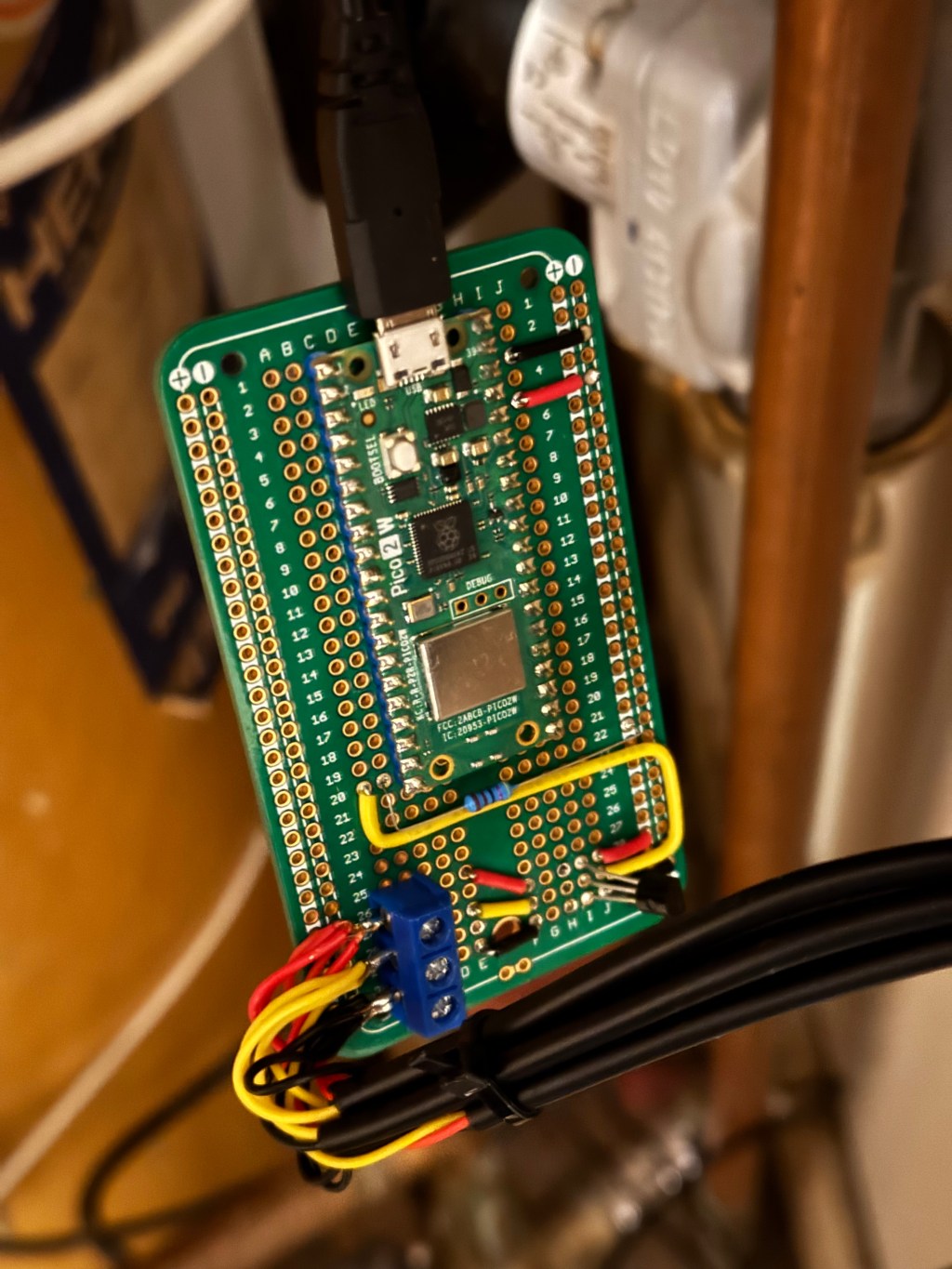
Using the board designed and tested in Temperature Monitoring – Part One, I picked up some DS18B20 sensors on longer wires and with waterproof ends.
They were run to the following locations:
- Through the loft to the cold water tank where it’s lowered until it almost but not quite touches the bottom of the tank.
- In the loft at approximately the height of the top of the cold water tank
- In the airing cupboard tied to the feed from the boiler to the valve
- In the airing cupboard tied to the feed from the valve to the hot water tank
- In the airing cupboard tied to the feed from the value to the radiators
The sensors come with a metal housing on the end, and so I made a makeshift strip from kitchen aluminium foil; about an inch wide and as long as the width of the roll. I wrapped this around the pipe once, and then included the sensor housing, before wrapping the rest of the tape around. I fastened with a couple of cable ties.

Due to the short distances in the airing cupboard, I placed the hot water and radiator sensors as far from the valve as possible to try and minimise the pick up of temperature conducted through the pipe itself, trying to minimise reading temperature on the radiator sensor when the water is being directed to the hot water tank, and vice versa.
There’s a 3 pin socket in the airing cupboard and so I replaced it with a socket that included a USB charging socket which allowed me to connect the board up in there.
The sensors were connected to the board and the software loaded.

You’ll have to ignore the state of the airing cupboard!
You can see in the top left, the feed from the 3 way valve into the hot water tank, and in the lower right you can just about see the sensor on the feed into the valve, and the sensor on the pipe just before it disappears into the floor to feed the radiators.

Issues
I noticed that the updates to the IOTPlotter API would stop, and require the pico to be restarted. I did some troubleshooting by running with Thonny connected via a long USB cable.
The call to the API would periodically have issues, either due to a brief outage of my broadband line, or (I suspect) possible maintenance of the API, etc. The code had not included a timeout on the API call, so I introduced one along with a try, except.
This reduced the issues but ultimately I had another idea to improve things, coming soon in part 3…

Leave a comment